3D Metrology Systems, Aerospace & Defense, Application Note, Custom Engineered Motion Systems, Hexapods, Integrated Automation Systems, Laser Scan Heads, Laser Systems, Medical Device Manufacturing, Motion Control Platforms, Optics & Photonics, Precision Manufacturing, Science & Research Institutions, Stages & Actuators, Test & Inspection
Application Note
Customized Relationships and Coordinated Motion with StatusGetAxisItemFast()
Many applications require custom coordinated relationships between a system parameter or ancillary motion equipment and the motion of the primary machine mechanics. Likewise, it is common to need custom kinematic transformations between a virtual programming coordinate frame and that of the real mechanics. Aerotech’s AeroScript programming language includes the StatusGetAxisItemFast() function as an ideal tool to program these relationships and transformations. The following example will show how this is done.
Example Relationship Development
A vertical Z axis following the height of a defined spherical surface as the X and Y axes are independently programmed to move over that surface is a simple example of a custom programmable relationship. This example comes from a real-world application and is a good introduction to the usefulness of customized programmable relationships within coordinated motion systems.
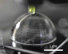
Figure 1 shows a 3D printed antenna array being deposited on a partial hemisphere. The ability to maintain the tool tip’s position relative to the surface in coordination with the X and Y motion is greatly simplified by programming the known spherical relationship of X, Y and Z axis positions into the motion controller. The user can then simply program the desired projected 2D profile in X and Y coordinates with Aerotech’s CADFusion 2D graphical motion development tool, and the profile will be correctly re-projected onto the desired hemisphere because the Z axis will implicitly follow the programmed spherical relationship. This custom relationship is easily programmed using two Automation1 programming features: the StatusGetAxisItemFast() function and the TrajectoryDelayTime parameter. These two features provide a wide range of capability for users to program custom coordinated relationships between system variables and axis motions, and they are straightforward to use.
For this simple hemisphere example, first let us define the relationship to be programmed into the Z axis trajectory generation. Figure 2 depicts a side projection of the hemisphere where a known zero location has been established at the apex. For any point in the X,Y plane a defined Z axis position can be established based on the nominal radius of the hemisphere. Knowing the radial distance from the hemisphere’s axis through X and Y position commands, a triangle can be drawn where the legs are R, K, and √(Xpos2+Ypos2). Through Pythagoras’ theorem we get Equation 1.
K=√(R2-(Xpos2+Ypos2)) (Eq. 1)
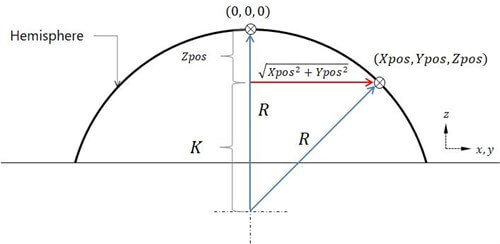
Additionally, it’s clear from Figure 2 that Equation 2 is also true.
Zpos=R-K (Eq. 2)
Combining the two we end up with the relationship to be programmed into the Z axis trajectory as a function of X and Y position commands (Equation 3).
Zpos=R-√(R2-(Xpos2+Ypos2)) (Eq. 3)
Now that the desired motion relationship between the Z axis and the X and Y axes has been established, we can learn to program this relationship into the Z axis trajectory and then learn to synchronize it with that of the X and Y axes.
Programming with StatusGetAxisItemFast()
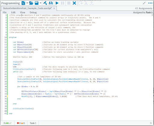
A sample AeroScript code usable in Aerotech’s Automation1 Studio application has been provided in Appendix A. It shows the steps required to execute a dependent Z axis trajectory generation per the relationship established in Equation 3 with the X and Y axes trajectories. Since the Z axis trajectory is dependent on the X and Y trajectories, the StatusGetAxisItemFast() function must be used to collect the X and Y position commands at the motion update rate. The “MotionUpdateRate” parameter in the system configuration file sets the trajectory generation frequency for each axis. Generally, the maximum motion update rate is 20 kHz for servo stages. In the coding example, an 8 kHz MotionUpdateRate setting is assumed for all axes.
The StatusGetAxisItemFast() function allows the user to collect different data items at the rate at which they are generated. In this instance, we collect the AxisDataSignal called “PositionCommandRawUnfiltered” from the X and Y axes. This raw, unfiltered signal must be used so that no irreconcilable filtering delay is built into the calculated Z axis trajectory. This allows the Z axis to be properly re-synchronized with the X and Y axes using a trajectory delay. You cannot achieve synchronization between all axes if you use the filtered command signal.
The StatusGetAxisItemFast() function can be seen in lines 27 and 28 of the sample code. AeroScript “critical” code blocks are executed at a 1 kHz rate. In the sample code, everything is contained within a CriticalSectionStart() function and a CriticalSectionStart() function block. Therefore, to capture the full 20 kHz of X and Y trajectory signals in a 1 kHz task execution, 20 data points must be captured and populated into an array each time the CRITICAL code executes. The number of data points captured with each execution of the StatusGetAxisItemFast() function is defined by the last argument in the command line. Now that the X and Y trajectory points are in an array, they can be used to calculate the Z axis position for that cycle’s 20 trajectory points. To see a full list of what data items can be collected by the StatusGetAxisItemFast() function, visit the Controller Status Function and AeroScript Enums Automation1 help file topics, respectively.
To calculate the Z axis trajectory, a simple ‘for’ loop structure is built to walk through each XY command location and calculate the corresponding Z axis command per the spherical relationship established with Equation 3. At the end of the for loop is a MovePt() (Position and Time) function, where the Z axis is commanded to the calculated position in the specified time interval of 1/20 of a millisecond, corresponding to the twenty times the ‘for’ loop will run in the 1 millisecond long critical code section. This matches the trajectory rate of the X and Y axes of 20 kHz. After all twenty Z axis positions have been calculated and commanded, the next twenty X and Y trajectory points are collected and the process is repeated as long as the relationship is enabled.
With the sample code running in a background Task, primary motion is commanded to the X and Y axes in another Task. The Z axis will always follow the spherical surface defined in Equation 3, regardless of where X and Y are commanded to go. The last problem to solve is synchronization.
Synchronizing Trajectories
The user must implement a trajectory delay on both the X and Y axes to synchronize the motion of all three axes. Because the Z axis is left to react to commands being sent to the X and Y axes, it is inherently lagging behind in its execution of its trajectory compared to the X and Y axes. The execution of the critical code section takes 1 millisecond, and there are additional delays from collecting the X and Y trajectories from the machine controller. To compensate for the delays seen in the Z axis, the user must go into the system machine controller definition (MCD) file and configure a TrajectoryDelayTime to the X and Y axes. This parameter can be found in the Automation1 Studio application, in the configure workspace under Axes>Motion>Trajectory. This parameter adds an initiation delay in the X and Y trajectory execution of the same magnitude as that seen by the Z axis due to the relationship calculation. Thus the axes are perfectly re-synchronized.
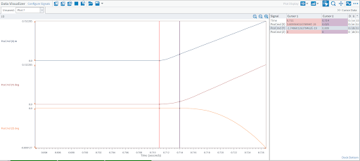
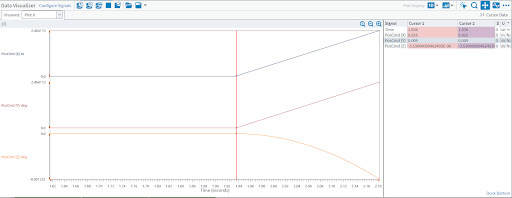
The required value of the TrajectoryDelayTime, set in milliseconds, depends on the system arrangement and the drives being used. In this instance, a delay of 3 milliseconds was needed to account for the code execution and the delays associated with the drive hardware used. The simplest way for a user to determine the correct delay is to measure the phase lag seen in the Z axis command stream relative to that of the X and Y axes in the Automation1 Studio’s Data Visualizer module prior to setting the TrajectoryDelayTime. Figure 3 shows a captured data in the Data Visualizer plot feature. This shows that the Z axis command stream lags behind that of the X and Y axes.
Using the left and right cursor lines, the required 3 millisecond delay can be easily measured. Figure 4 then shows the same motion line after a 3 millisecond delay has been implemented in the X and Y command streams via the TrajectoryDelayTime parameter. You can see that motion on all three axes is now synchronized to the exact same trajectory generation cycle.
Conclusion
While this example of a Z axis tracking a spherical surface is simplistic, the concepts used here provide a very powerful capability to the user when it comes to non-linear custom kinematics programming. Extremely complex functional relationships and kinematic transformations between the motions of large numbers of axes, both real and virtual, can be programmed directly in the AeroScript language. Axes whose trajectories are dependent on the motion of other axes and non-linear custom kinematic transformations are a common problem in many complex automation applications. Additionally, you can form relationships that aren’t solely based on position. One could program the position of a subordinate axis based on a function of another axis’ velocity commands and/or acceleration commands, in addition to position. The StatusGetAxisItemFast() function gives users the versatility to prescribe any kinematic relationship they can think of between real and/or virtual axes alike, while the TrajectoryDelayTime parameter allows the motion execution to remain synchronized.
Appendix A
Sample AeroBasic Code