3D Metrology Systems, Application Note, Data Storage, Integrated Automation Systems, Motion Control Platforms, Optics & Photonics, Piezoelectric Nanopositioners, Precision Manufacturing, Science & Research Institutions, Semiconductor, Stages & Actuators, Test & Inspection
Application Note
Motion Control with Precision Noncontact Displacement Sensors
Introduction
Noncontact displacement sensors are used in measurement applications where surfaces or processes do not allow contact and demand high precision. Capacitive, confocal, eddy-current and laser triangulation sensors have proven themselves in applications that incorporate motion systems. Noncontact sensors are available in many different versions. However, sensor range decreases significantly as the required precision increases.
Despite the range restriction, there are still numerous products on the market from which the appropriate sensor can be chosen for a certain application. The following content briefly explains each displacement sensor technology to help simplify your selection.
Please note that not only the sensor itself is responsible for the achieved precision, but rather the combination of electronics, signal processing and environmental conditions.
Eddy-Current Measuring Principle
Strictly speaking, the eddy-current principle should be classified as the inductive measuring principle. Measuring via eddy current is based on the extraction of energy from an oscillating circuit. This energy is needed for the induction of eddy currents in electrically conductive materials. Here, a coil is supplied with alternating current whereby a magnetic field forms around the coil.
According to Faraday’s Law of induction, if an electrically-conducting object is present in this magnetic field, eddy currents are produced in it. According to the Lenz Rule, the field of these eddy currents is opposed to the field of the coil, which causes a change in the coil impedance. This change in impedance can be outputted as an absolute distance.
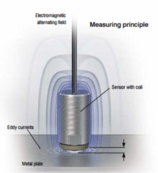
Eddy current sensors are useable on all electrically conductive objects with ferromagnetic and non-ferromagnetic features and can be used to “see through” non-conductive objects. They typically have small sensor sizes. Eddy current sensors are often used in applications where harsh ambient conditions are present and where “medium” precision is required. Immunity to dirt, pressure and extreme temperature are key performance features, making them ideal for applications such as where a motion system uses the sensor for focus height adjustment in a laser machining environment. Output signal and linearity depend on the electrical and magnetic characteristics of the target material, so the sensor needs to be calibrated to the material under test. Sensor diameter and effective measurement spot diameter increase with larger measuring ranges. However, this can be used to average-out the surface with a larger spot size.
Capacitive Measuring Principle
The capacitive measuring principle is based on how an ideal plate-type capacitor operates. If an alternating current of constant frequency flows through the sensor capacitor, the amplitude of the alternating voltage on the sensor is proportional to the distance to the target (ground electrode). In practice, due to the design of the sensors as guard-ring capacitors, almost ideal linear characteristics are achieved. Capacitive sensors can also measure insulated materials.
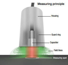
Advantages of capacitive sensors include a constant sensitivity and linearity for all conductive objects. They also have high temperature and signal stability. Capacitive sensors boast subnanometre resolution with good linearity. Capacitive sensors are ideal for large, flat surfaces in a relatively clean environment, so laser applications where plume is produced in the measurement area should be avoided.
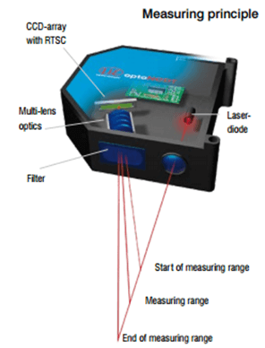
Laser Triangulation Measuring Principle
Laser triangulation emits a laser beam which is aimed at the target. The light spot reflected from the target is imaged via a lens either on a CCD/CMOS array or on a PSD element. The intensity of the reflected beam depends on the surface of the material. The distance from the object to the sensor is calculated from the position of the light spot on the receiver element. The data is evaluated in the internal controller and output via various interfaces.
Advantages of laser triangulation devices are a small measurement spot diameter, a large offset distance between measurement object and sensor, large measuring ranges, and that it’s almost independent of material type. However, the measurement accuracy is influenced by shiny and matte surfaces, and the beam path must be a clean environment free of any obstructions. Also, laser triangulation has a large sensor dimension in relation to confocal, capacitive and eddy current sensors, and for reflecting surfaces special sensor alignment is required. Highly complex surfaces may disrupt the beam from returning to the sensor, causing data interruptions.
With these limitations in mind, laser triangulation can offer low-cost, fast scanning of surfaces. But again, laser triangulation is not suitable where debris can find its way into the beam path.
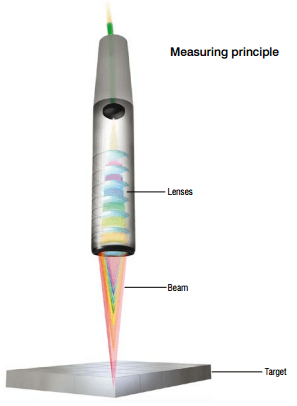
Confocal Chromatic Sensor Measuring Principle
Polychromatic light (white light), starting from the light source in the controller, is transmitted to the sensor via an optical fibre. The lenses are arranged so that the light in the longitudinal direction of the optical axis is broken down by controlled chromatic aberration into monochromatic wavelengths. A lens focuses the light onto the target surface. Depending on the distance, there is a particular spectral colour (wavelength) in focus. In the sensor system, the wavelength of light exactly focused on the target is used for the measurement. The light reflected from this point is imaged by an optical arrangement onto a light sensitive sensor element, where the associated spectral colour is detected and evaluated. A defined distance point is assigned to each wavelength by factory calibration.
This principle enables measurement on practically all surfaces, including transparent or translucent. Advantages of confocal sensors are an extremely high resolution in the nanometre range; surface-independent measurement; a small, constant measurement spot; and a compact beam path. Restrictions would be a relatively limited distance between sensor and measurement object, a clean environment required in the beam path and cost — these sensors are typically more costly than the other technologies discussed here.
Using Displacement Sensors with Advanced Motion Controller Features
Autofocus – Vertical Height Control
Aerotech’s Automation1 motion controller has the ability to enable an outer tracking loop that works in conjunction with a servo or stepper motor. A displacement sensor can be used as the feedback device. Typically this is used to control vertical height within a system. The sensor’s analog output voltage is used as the feedback and is fed directly into the motion controller analog input. The Autofocus feedback loop uses a simplified PID loop that can be set up to continuously maintain a height from a surface – for example, focusing a camera or laser, or for reaching a target position. A deadband can also be applied so that the axis will not continuously hunt.
Sudden accelerations in the axis can be limited by setting our Acceleration Limiting feature, so sudden changes in the position command caused by enabling Autofocus can be reduced or eliminated. In the same way maximum tracking speed can be specified by a speed clamp value. Upper and lower limits of the tracking range can be set so that holes and edge areas can be accounted for to stop the axis from large fluctuations in height.
Position Synchronized Output (PSO)
Aerotech controllers have the ability to take up to three encoder inputs and combine these to create a one- to three-dimensional path tracking ability. Within this path the controller can output highly accurate synchronised pulse generation features referred to as the PSO (Position Synchronised Output). This is typically used for modulating laser power, triggering an external hardware device or synchronizing data capture on sensor inputs. The PSO has low jitter and low latency specifications as it is carried out in hardware rather than software.
PSO consists of two main functional blocks: the distance counter(s) and the pulse generator. The distance counters generate a “firing event” after a specified distance is traveled. This event can be directly fed into the sensor electronics so that the displacement data can be logged. The distances can be either fixed or contained in a drive array. This therefore can be used to build-up continuous data of a surface or focus on specific features of a part under test.
Because the PSO data can be one-dimensional, simple line scans like rastering can be implemented by most of the Aerotech range of motion controller hardware. Two dimensional XY part data capture can be carried out by devices that have dual PSO capability, and more complicated 3D space or helical paths can be obtained by those with triple PSO functionality.
Drive Data Capture Fast Data Acquisition Feature
The Drive Data Capture AeroScript function on the Automation1 controller can be used in conjunction with the PSO functionality to record data on the motion controller rather than storing the data directly on the sensor electronics. This is normally the analog value that can be captured when a PSO firing event occurs. In the case of a confocal sensor, the analog data may be intensity rather than distance, which can be used to determine other features of the part under the sensor.
In the reverse way, an external source or other event generated can begin a data recording event on the motion controller using its high-speed inputs. Again, the displacement or intensity can be recorded, or the position from various encoder inputs.
Position Feedback Using the Sensor Output
Another use of the analog output of the sensor electronics can be a nontraditional form of position feedback. Unlike the Autofocus method, which retains the normal feedback device, the motion controller can specify the analog output of the sensor electronics as an absolute primary feedback either in conjunction with another device (velocity loop) or as the sole feedback. This may be useful where the analog sensor is used as a high-resolution feedback device over a relatively short distance, with the use of a sensor type where a traditional motor encoder is not suitable or where the sensor cannot be located in the measurement area.
Encoder Feedback into the Sensor Electronics
It is possible to capture the data of up to three separate incremental encoders directly into the sensor electronics. This allows encoder data to be synchronised with displacement and, where applicable, intensity data. The controller can echo-out the connected data directly and can also convert (with the appropriate hardware) non-incremental encoder types into incremental format.
LabVIEW®/.NET
Aerotech motion controllers have libraries and LabVIEW VIs (virtual instruments) that — in combination with the equivalent from the sensor manufacturers — can create powerful front-end and analysis software.
Aerotech would like to recognise the expertise and assistance provide by Micro Epsilon UK in creating the information presented above including the images. Micro Epsilon is a world-leader in the manufacture of noncontact displacement sensors.